By Sean Heber
Even though I’m a software engineer at heart, I’ve always been fascinated by electronics. When I was a kid, I had a Radio Shack 130-in-1 Electronics Project Kit that I’d fiddle with from time to time, but I never studied it quite enough to truly understand how the circuits really worked. My mind was always more digital.
In the late 1990s, my dad and I started getting into amateur radio. I had found an old book on his shelf about Morse code and was trying to learn it just for fun (I never got good at it). When dad found out, he went all-in on our getting real licenses. He bought some radios and set up some antennas. We passed the tests and joined the local radio club.
That introduced me to the world of hamfests, which are swap meets where amateur radio hobbyists buy and sell all sorts of things. Ever the computer nerd, I was more fascinated by the vendors selling software and computer hardware than I was about any of the radio stuff. But it was as a teenager at a hamfest when I first realized I could buy standalone digital chips—something I had never even considered before.
I didn’t have much money, but I spent some of it on a handful of logic chips thinking I could build my own computer. Of course, I didn’t know nearly enough to do something so ambitious, but I did manage to use them to assemble a 4-bit binary adder without using someone else’s schematic! Software came more naturally to me, though, and was far less expensive, so I put my electronics stuff away for a long time. Fast forward a couple of lifetimes. I was looking for something to do that was computer-like but didn’t involve writing any code when I remembered my old electronics stash.
I started making YouTube videos exploring the process of trying to learn how electronics really worked. Since I still had the old TTL parts I’d collected over the years, I used them
as my starting point.
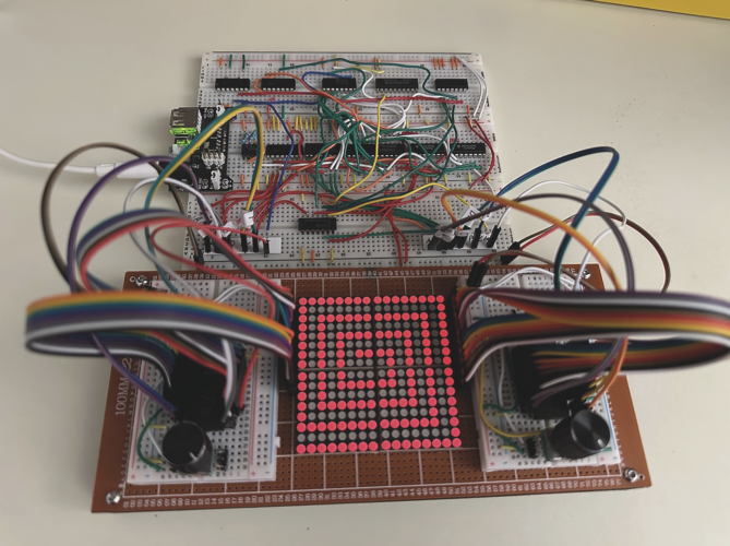
After a few months of tinkering around, I decided it was time to make something bigger. Since I didn’t know what I didn’t know, I foolishly decided to build an electronic Etch A Sketch entirely from TTL logic—no microcontroller and no code. I had to learn a lot of basic things and I made some mistakes, but I ultimately got it to work! The circuit has a 16×16 screen for a total of 256 individual LEDs. A timer ticking an 8-bit counter cycles through all of them, one-by-one, hundreds of times per second, checking the RAM to see if the LED at that location should be lit or not.
Two rotary encoders drive two more counters that act as horizontal and vertical input addresses. When the screen and input addresses match, a bit is written to RAM. After adding some extra logic to clear the screen at the push of a button, I suddenly had my Etch A Sketch!
I had a lot of fun building this project and I uploaded a video about it to YouTube (bit.ly/4fmE39n). I know the technology I used is old and out of date, and I’m
far from being an expert, but sometimes the best way to learn how the future works is by understanding what came before.
Got a design project you’d care to share? Contact our Editor: max@designing-electronics.com